On the “Soldering Sunday” site a few years ago I found a fun little LED circuit board in the shape of a robot that could be used as a starter kit in the world of electronics and soldering. Unfortunately, the project seems to have come to an end and the shop for the circuit boards no longer existed. Since I found the Pixel Pal “Chip” so cool, I recreated it. I was hoping that my kids would think the character was cool too, and then they’d want to recreate it… well, never mind. I had my fun!
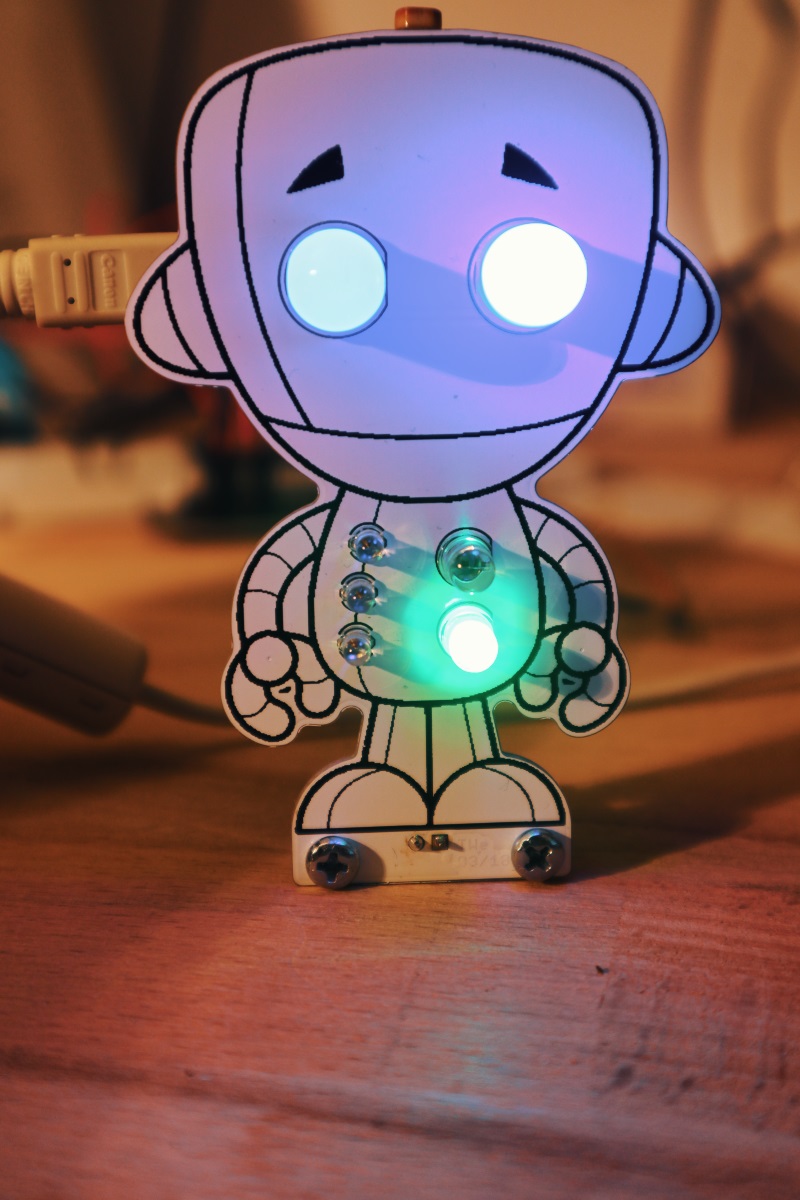
Blinky Bot in Action
In the original, “Chip” only consists of two LEDs and two resistors. Anyone who knows me knows that I don’t even heat up the soldering iron for only two LEDs! Accordingly, “Chip” now has two 10mm Leds as eyes and three 3mm Leds + two 5mm Leds on the body. The LEDs are controlled directly via an Arduino Nano, which is plugged into the back of the circuit board. I chose the Arduino Nano because I thought that the figure could then be programmed by my children, e.g. via Scratch. Then they could graphically slide simple Blink programs together. “Chip” also has an LDR resistor on top of the head, which is used as a brightness sensor to later trigger any reactions in the firmware. On the back of the board there is also a socket with the I2C signals of the controllers so that additional sensors can be connected there.
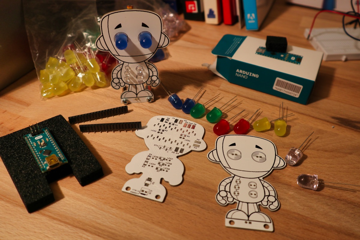
Blinky Bot Parts
Here are the technical documents for the small blinking Bot…
PDF-Schaltplan
PDF-Layout
Gerber-Daten Layout
LibreCalc-Table for the resistor calulation
Arduino Test Projekt
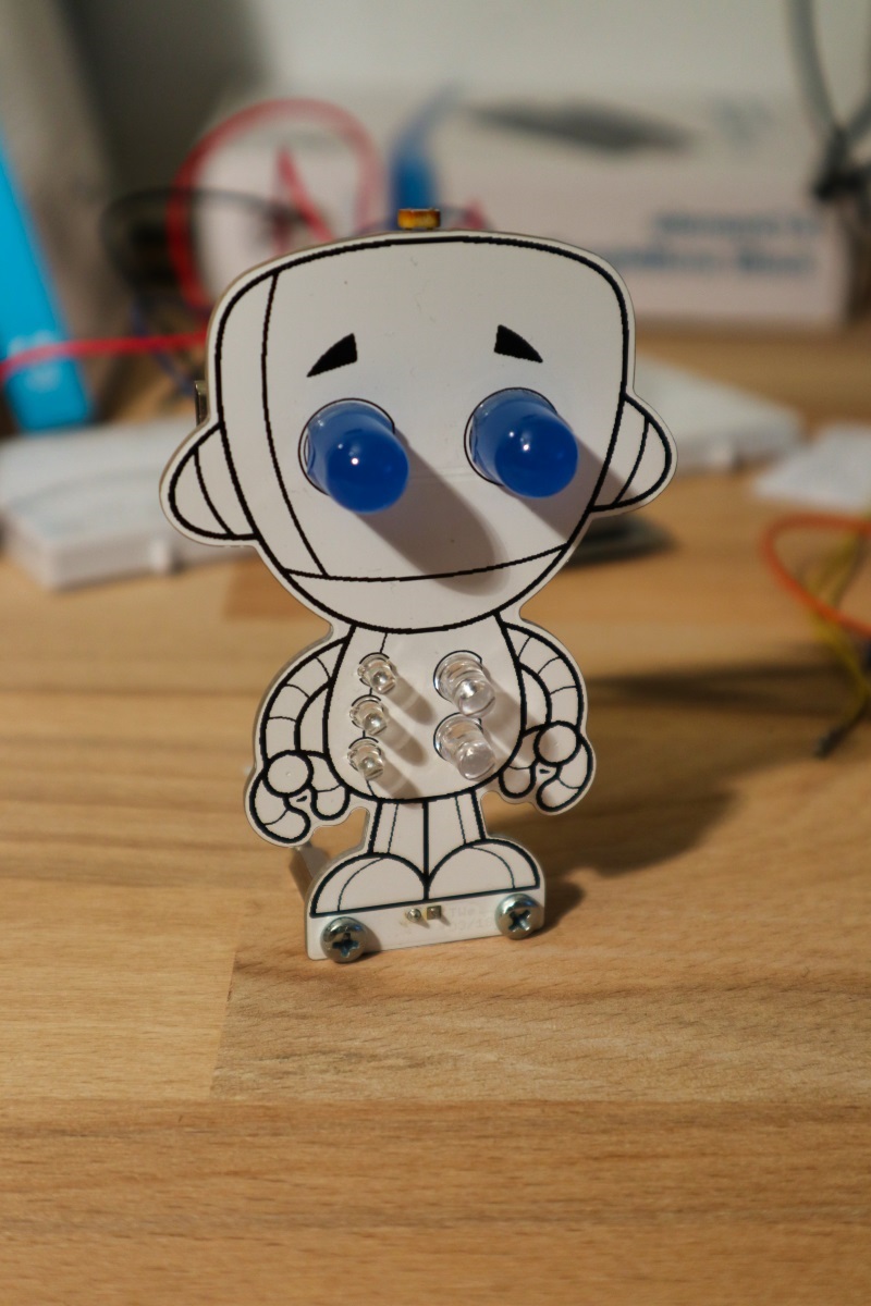
Blinky Bot Board frontview

Blinky Bot Board backview
There is not much to say about the circuit itself: the LDR sensor is connected to one of the analog inputs of the Arduino via a simple voltage divider. The LEDs are connected directly to the IO pins of the Arduino and are connected to series resistors. Depending on the LEDs used, the series resistors should be adjusted accordingly. (Led’s are quite bright these days, so maybe test in advance which values are suitable without the LEDs glowing for hours on the retina… 😃) The power supply is either via the USB connector of the Arduino or via the 2- Pin connector at the bottom of the feet. The diode in this supply branch serves as reverse polarity protection.
I ordered the circuit boards directly from Seeed in China. The circuit boards didn’t cost €20, I mean, and the quality was okay.
Status: April 2018