Project idea
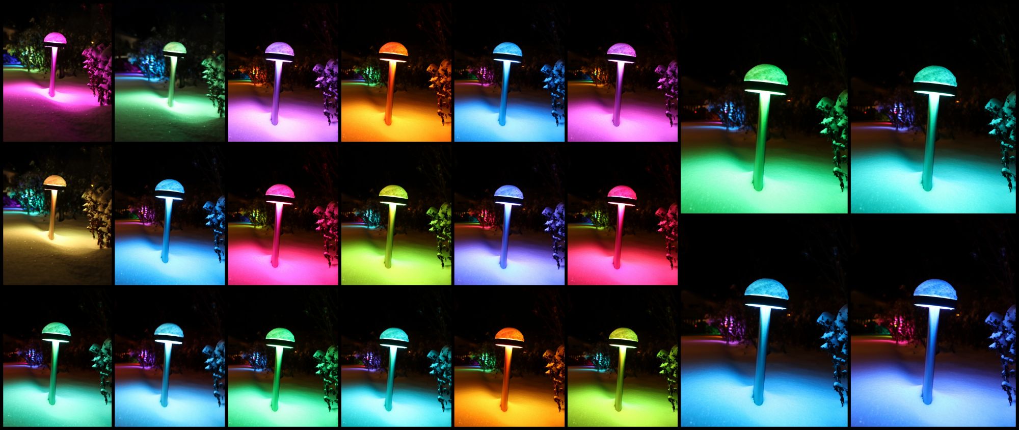
The goal of this project is to build chilled RGB garden lighting for the terrace that is controlled via WiFi. Before long explanations follow, first a picture of the end result:
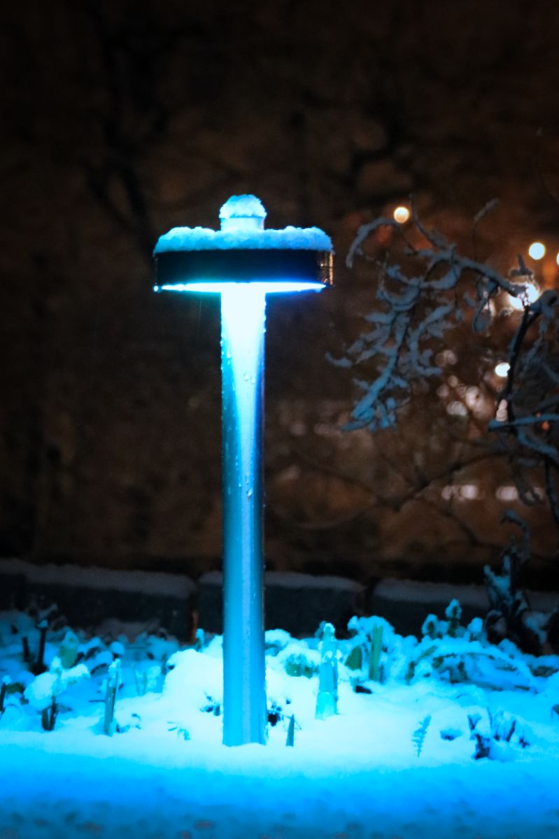
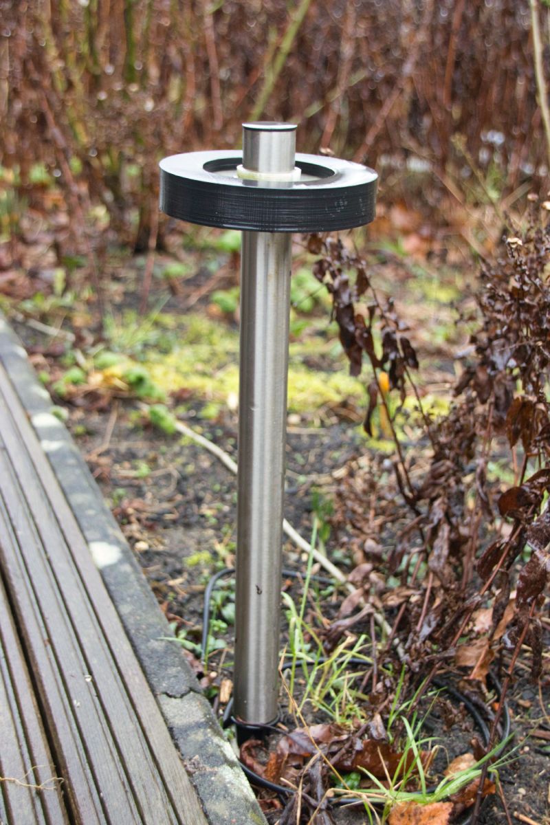
Garden lamp in the snow
The standpipe for the lamps are stainless steel tubes left over from defective solar lamps. The ring above consists of two parts that have been 3D printed. The outer black ring of the lampshade contains an RGB LED strip with 22 WS2812 LEDs. The inner part of the ring is printed in transparent PLA. This part serves as a diffuser for the light and also as an attachment to the lamp tube.
The Electronic
The colors of the WS2812 LEDs can be controlled individually. For this purpose, the LEDs hang in a so-called daisy chain, i.e. the control data is looped through the LEDs and passed on to the next LED. Details on the control of the WS2812 can be found e.g. here. Theoretically, you should be able to bridge a distance of 5m between two LEDs. In my experience, however, this rarely works in a really stable way.
Another problem arises from the fact that a total of four lamps are to be hung one behind the other on a cable. I.e. 22 LEDs * max. 60mA * 4 results in a maximum current of approx. 5.28A at 5V. The total cable length should be a little over 12m. The voltage drop on the long cable would cause the operating voltage to drop below the 4.5V range and the LEDs would no longer function reliably.
The solution to both of these problems is a small driver board with a DC/DC converter that generates +5V locally in each lamp from +24V. A small Traco TSR1-2450 is used for this, which supplies a maximum of 1000mA output current. This reduces the maximum current on the line by a factor of almost 5. In addition, data is transmitted between the lamps via an RS485 driver with differential signals that are very insensitive to interference. The TI SN75LBC180 was used there because the receiver output of this component supplies CMOS levels. The cheaper version, which is also easier to get, the SN75ALS180, only delivers TTL levels, which are actually outside the valid level range for the WS2812B.
Here is the circuit diagram and the layout of the driver:
- PDF Schematic WS2812-DiffDriver
- PDF-Layout WS2812-DiffDriver
- PDF-BOM WS2812-DiffDriver
- Gerberfile 10-panel WS2812-DiffDriver
The size of the circuit board is chosen so that it can be easily accommodated in the standpipe of the lamp.
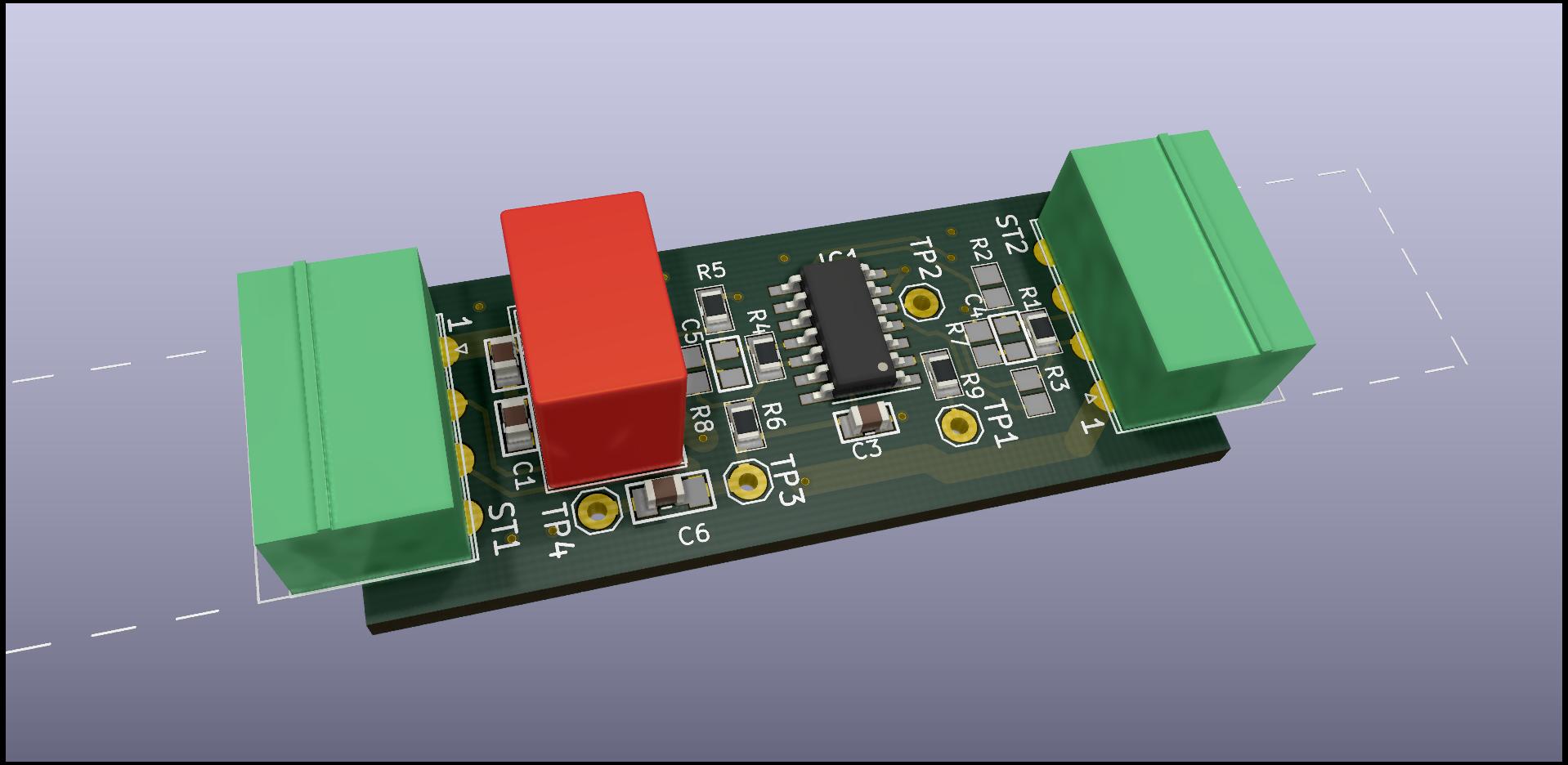
3D-Boardview
The lamp group is controlled via WLAN via an ESP8266 module (Nodemcu). The firmware for this is not self-made, but the OpenSource project WLED is used directly. You can easily select various color patterns etc. via a beautiful web interface. There is also a timer control, connection to MQTT broker & home assistant etc.
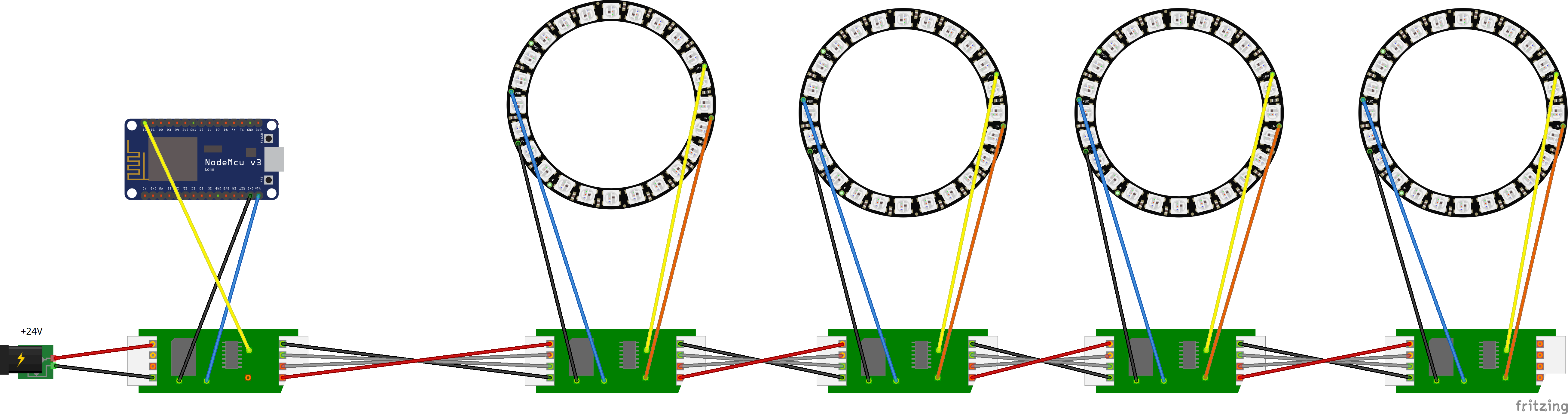
Interconnection
The ESP8266 module is also supplied with +24V via one of the driver boards. Half of the driver module is used as an RS485 converter. This module is housed in a waterproof plastic case along with a power supply.
The mechanics and assembly
The STL files for 3D printing:
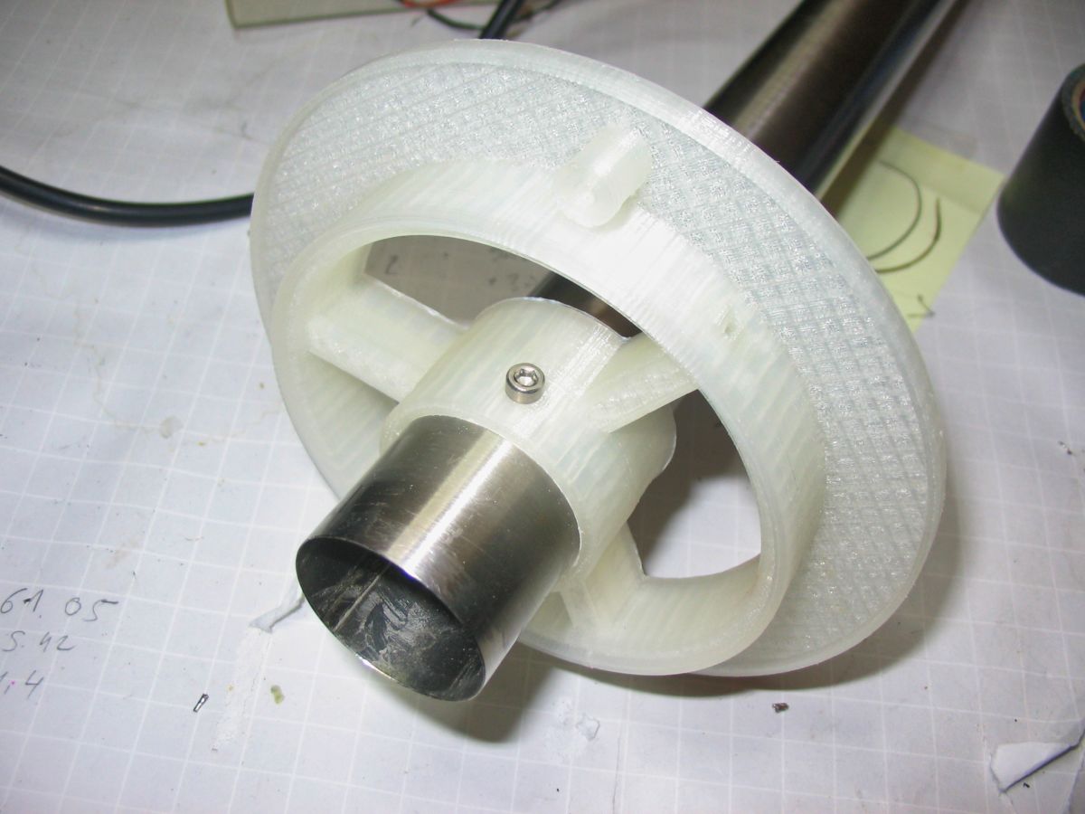
Diffusor monitored
The ridges in the diffuser between the lampshade and the retaining ring are hollow. The cables to the Ledstrip are routed through there. The holes in the stainless steel tube should be at least 5mm in diameter. A diameter of 3.5mm is sufficient for the hole for the retaining screw.
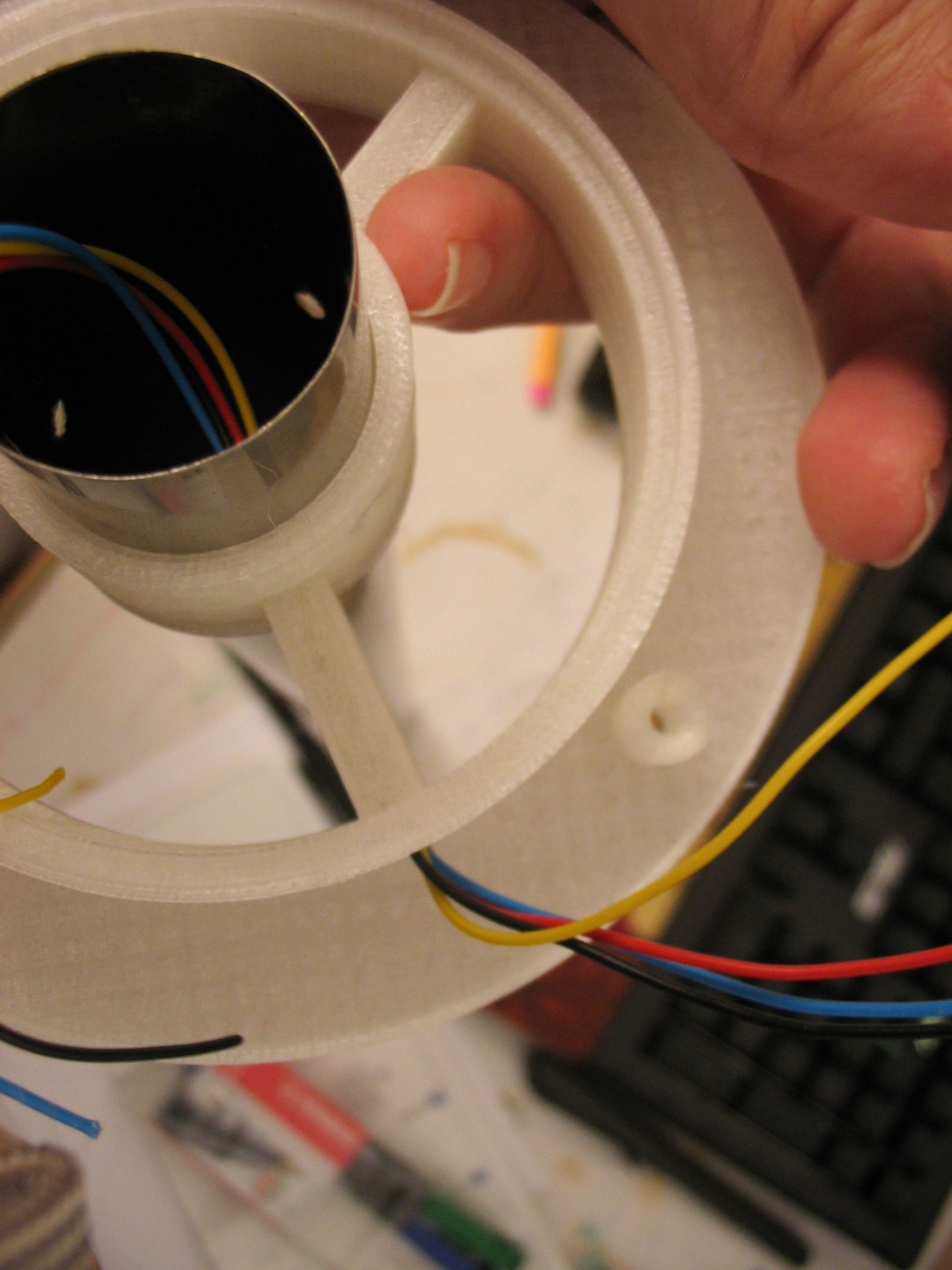
Cable bushing
The cables are soldered to the Ledstripe before they are glued into the ring.
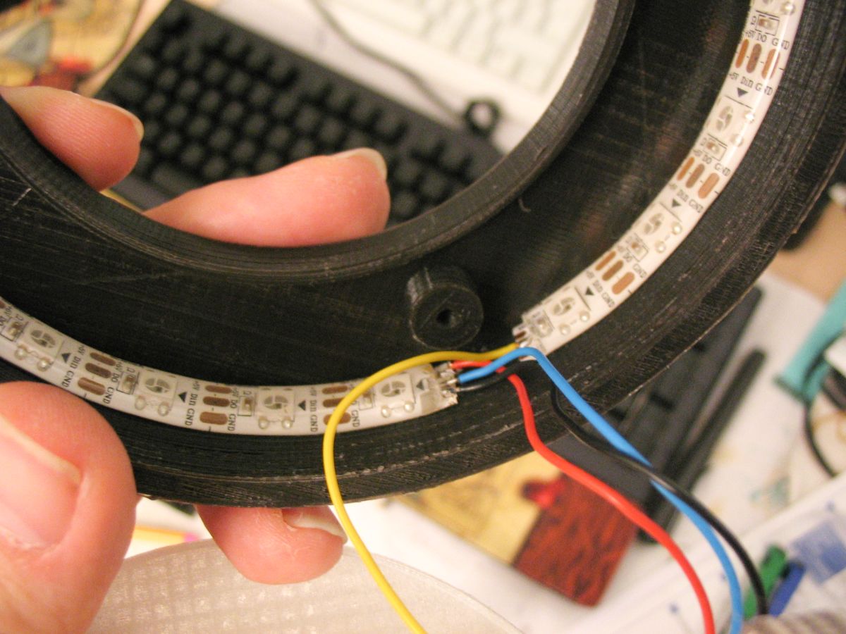
Outer ring with Ledstripe + cable
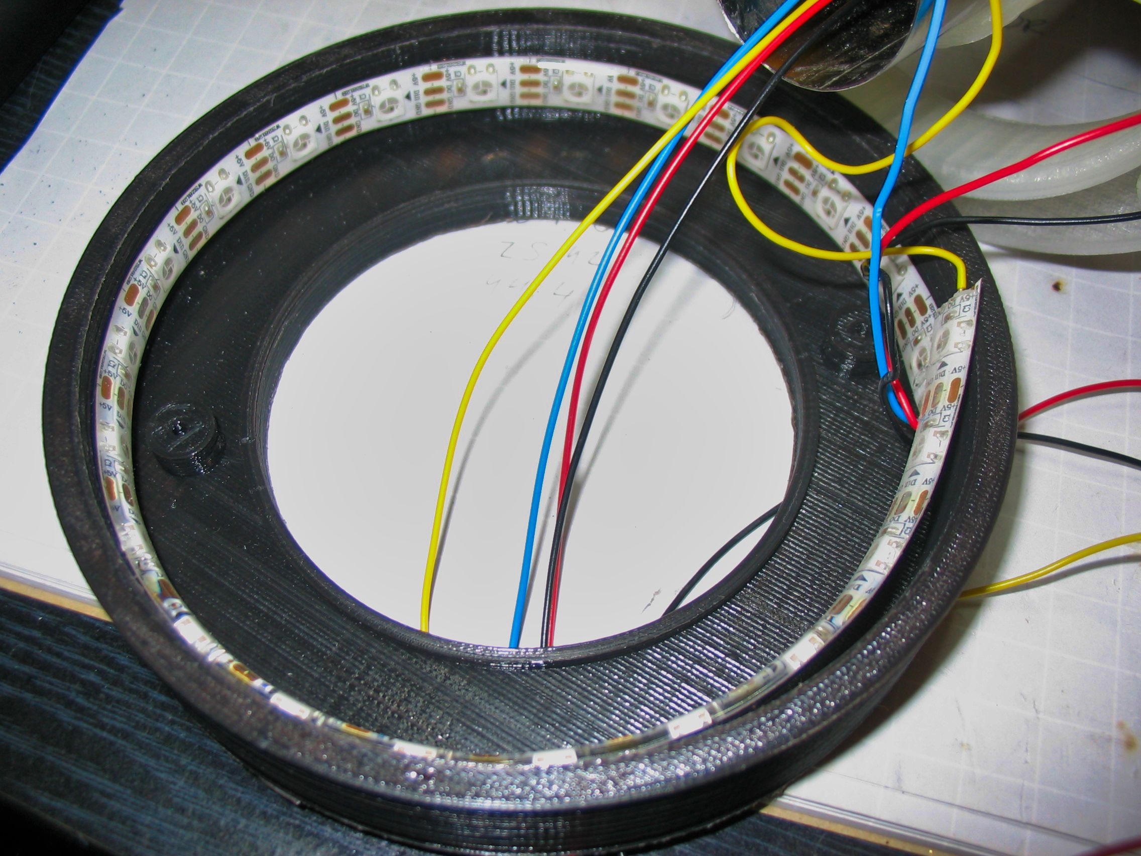
Outer ring complete
The assembly of the two lamp parts is a bit complicated, because when aligning the two parts, it is not easy to see whether the holes for the screw connection is in the right place. In addition, care must be taken not to pinch the cables. 15mm M3 screws are provided as screws.
The cable from the LED strip to the driver board should be left long enough so that the driver board can be pulled out of the standpipe by about 8 cm. The cables are soldered directly to the test points on the driver board. Then the back of the board and the soldering points are isolated with adhesive tape. The cables for the supply between the lamps are pushed through the standpipe from below and then a Riacon connector is connected. This is then used to connect to the driver board. Then the driver board is pushed back into the standpipe and closed with the cover.
Finished lamp

Experiences
The lampshades printed with PLA have withstood the weather and UV light for a few years. The way the lamp is constructed, there are no problems with water penetrating or the like. However, the stability of the LEDs outdoors is not satisfactory. LED strips protected by a protective layer against moisture are installed in the lamps. The lamps work without any problems over the winter, but from spring onwards, individual LEDs in the lamps always break. I don’t know if it’s related to temperature, humidity in the LEDs, or UV radiation. The soldering points of the LEDs are not the problem, but apparently directly the bonding wires in the LEDs. Many of the LEDs work again when you press on the LED housing from above. I once read in an article by an electronics manufacturer that the WS2812 are very sensitive to mechanical pressure during production. Maybe the LED strip I used was already damaged… In other projects with WS2812 strips, there have not been these problems so far.